Description
A compact link from tether to control station.
Power-line communication with Ethernet output
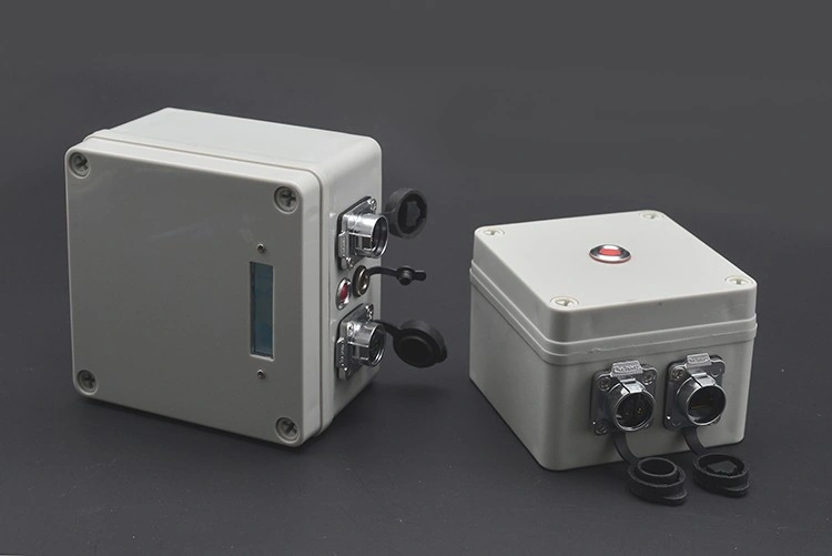
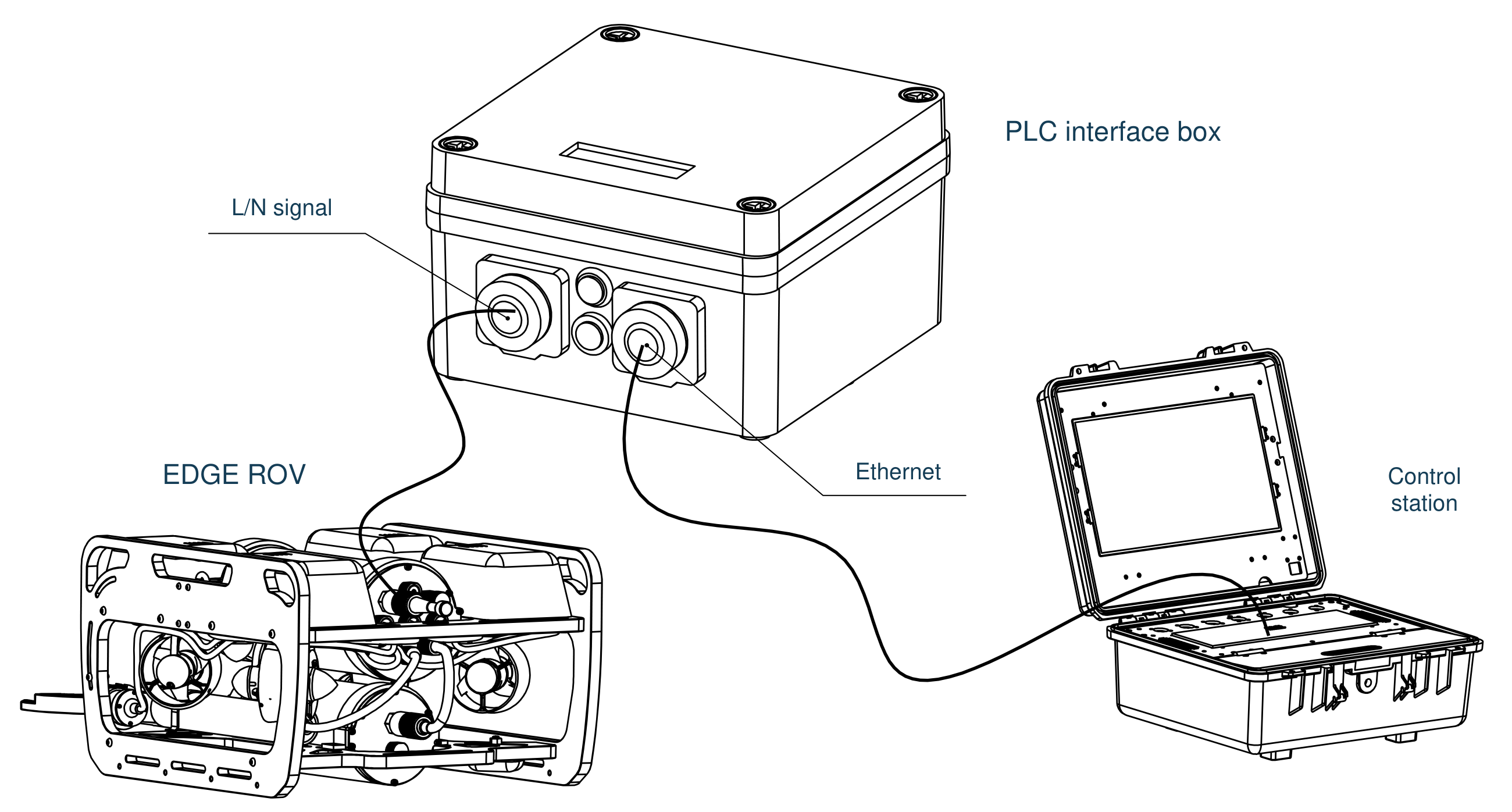
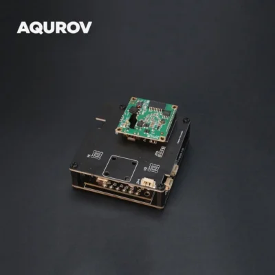
Bring the robot’s communication link to your control station through a compact topside interface. The built-in PLC module carries high-frequency signals over the L/N conductors of the tether, then presents the data through an Ethernet connection.
- 01Robot-side PLC moduleA compatible module inside the robot provides the other end of the communication link.
- 02Tether to the interface boxThe L/N connection carries the PLC communication signal to the topside unit.
- 03Ethernet to the control stationA network cable connects the interface box to the computer or control station.
Long-distance link
Specified for 300 m under the stated same-meter transmission conditions.
High-rate transmission
Up to 100 Mbps reported in the source test at 300 m; actual performance depends on the link.
Stable communication
High-frequency PLC transmission designed for stable signals and interference resistance.
Plug-and-play setup
An integrated enclosure keeps the topside interface compact and quick to connect.
Choose how you power the interface.
The same communication role, two power arrangements
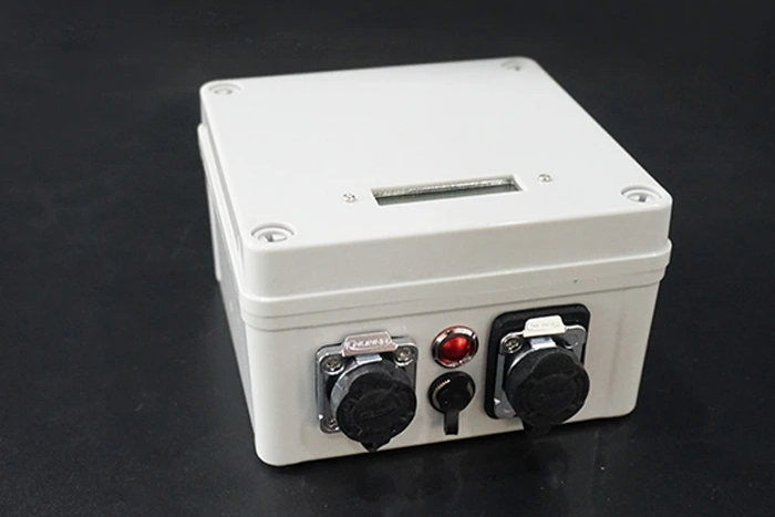
ROV-GROUND-VBATT-R1
Battery version
Choose the self-powered unit when you want the communication interface to run from its own internal battery.
- 3S / 18650 / 10,000 mAh battery
- Battery display and power switch
- Dedicated charging connection
- Ethernet and L/N signal interfaces
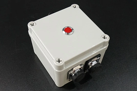
ROV-GROUND-SLIM-R1
USB-powered version
Choose the lighter unit when a USB power source is available at the control station.
- USB power; no internal battery
- Power indicator on the lid
- No battery display, charge port or switch
- Ethernet and L/N signal interfaces
Connections at a glance.
Original system drawing, translated into English
 View high-resolution drawing ↗
L/N signal interface
The two-conductor connection carries the PLC signal through the tether. A compatible PLC module is required at the robot end.
Ethernet interface
The network connection carries data between the interface box and the control station.
Version-specific power
The battery version has a charging connection, display and switch. The USB version is powered through its USB connection.
| Terminal 1 | L |
|---|---|
| Terminal 2 | N |
Technical specifications
Enclosure, link and module data shown separately
| Transmission method | High-frequency PLC over L/N conductors |
|---|---|
| Data output | Ethernet |
| Reported transmission rate | Up to 100 Mbps at 300 m under the stated same-meter test conditions |
| Transmission distance | 300 m, within the same electricity-meter range |
| Maximum nodes | 8 |
| Robot-side requirement | Compatible PLC module |
| Box power | Internal battery or USB, version dependent |
| Operating temperature | 0 to 70°C |
|---|---|
| Storage temperature | −20 to 70°C |
| Operating humidity | 10–90% RH, non-condensing |
| Storage humidity | 5–90% RH, non-condensing |
| Use location | Topside |
| Weather exposure | Rain and water-drop resistance stated in the original listing; not for submersion |
The 100 Mbps figure is a reported test result at 300 m within the same electricity-meter range. It is not a guaranteed throughput for every tether, installation or noise environment.
View full internal PLC module specifications
| Standards | HomePlug AV; IEEE 802.3; IEEE 802.3u |
|---|---|
| Networking features | TCP/IP; IGMP; CSMA/CA; QoS |
| Modulation | OFDM: 1024/256/64/16-QAM, QPSK, BPSK and ROBO |
| Frequency band | 2–28 MHz |
| Listed transmission rate | 100 Mbps |
| Data security | 128-bit AES encryption |
| Internal module supply | 12 V DC; 200 mA |
| Coverage reference | 5,000 sq ft, as listed for the module |
| Module interfaces | AC, Ethernet, DC, indicator and button connections |
|---|---|
| LED indicators | Power; power-line data transmission; Ethernet |
| Button function | Pair / Reset |
| Operating systems listed in module data | Windows 98SE / ME / 2000 / 2003 / XP / Vista / Windows 7; Linux; Mac OS |
These are internal module specifications. Module-level AC/DC interfaces and the 12 V / 200 mA supply rating do not define the external USB input rating or add an AC power inlet to the enclosure. The coverage figure is a module reference, not an underwater operating area.
Dimensions & installation reference
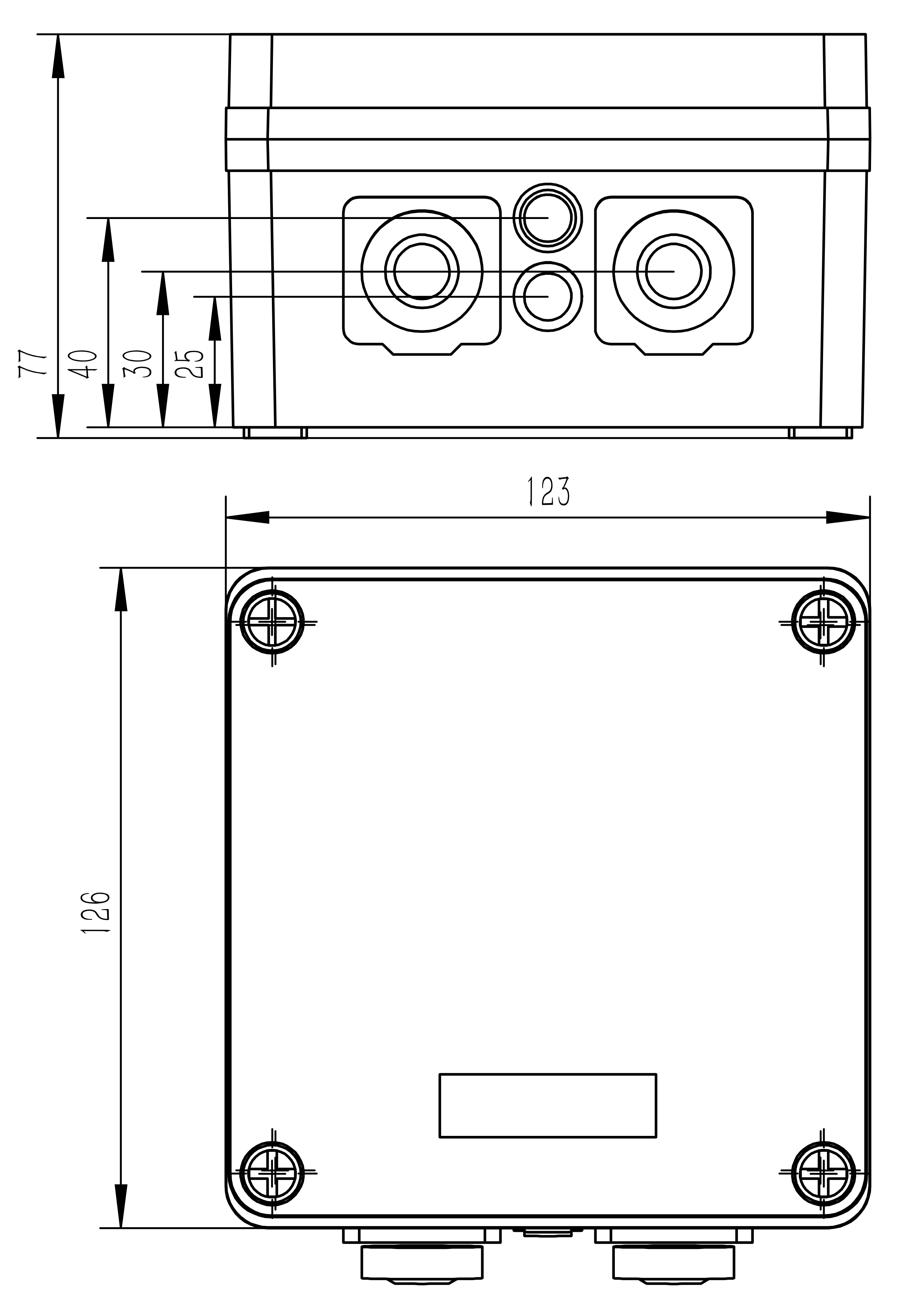
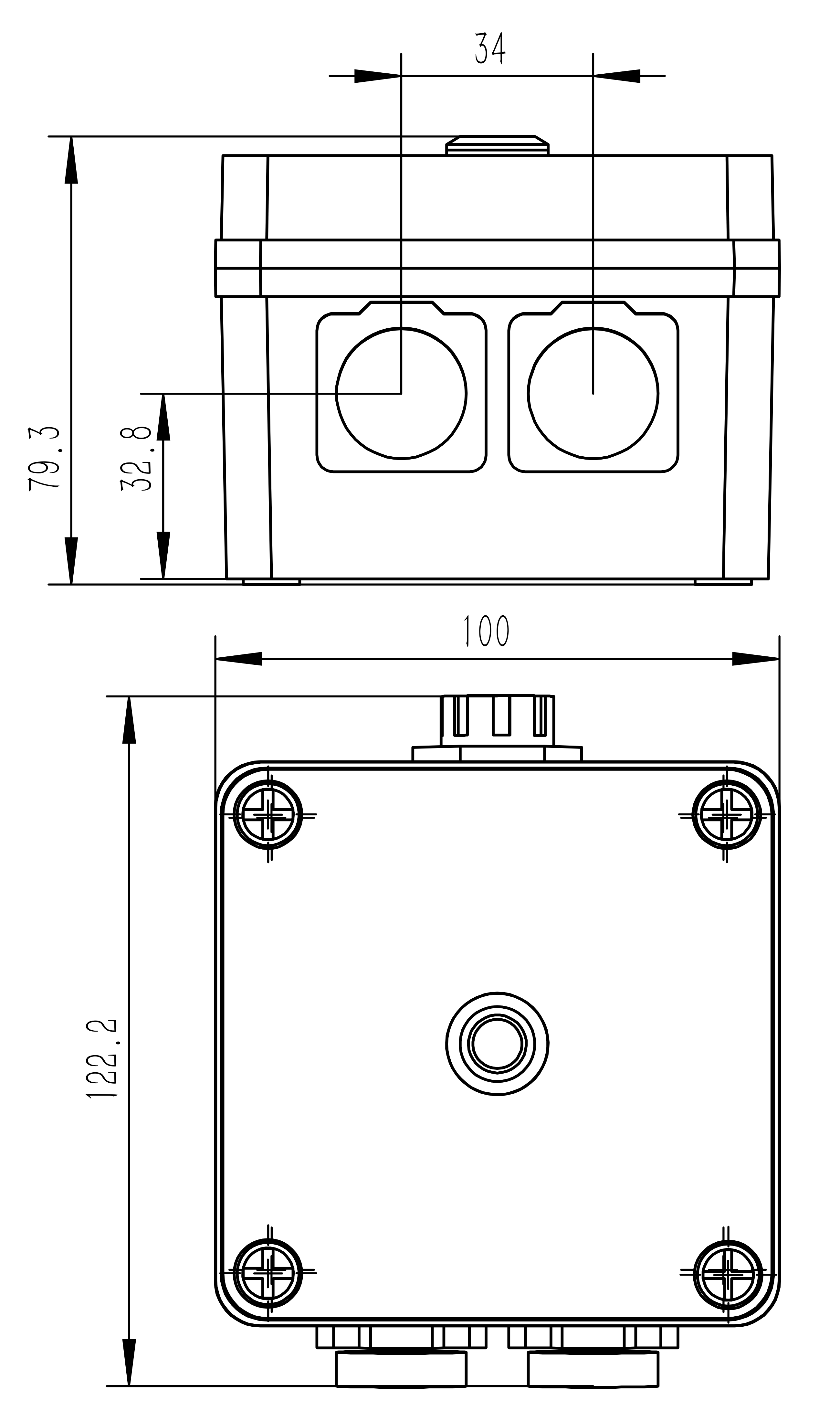
Original dimension callouts · millimetres
Battery version
 View high-resolution drawing ↗
123 × 126 × 77 mm
Additional interface-position callouts: 40, 30 and 25 mm.
USB-powered version
 View high-resolution drawing ↗
100 × 122.2 × 79.3 mm
Additional interface-position callouts: 34 and 32.8 mm.
Use the illustrated views when checking connector clearance and enclosure fit. Dimension values follow the supplied engineering drawings.
What comes with each version?
Kit components and clearly identified interfaces
Select the power arrangement that suits your control station. Explore each kit and its connection points below.
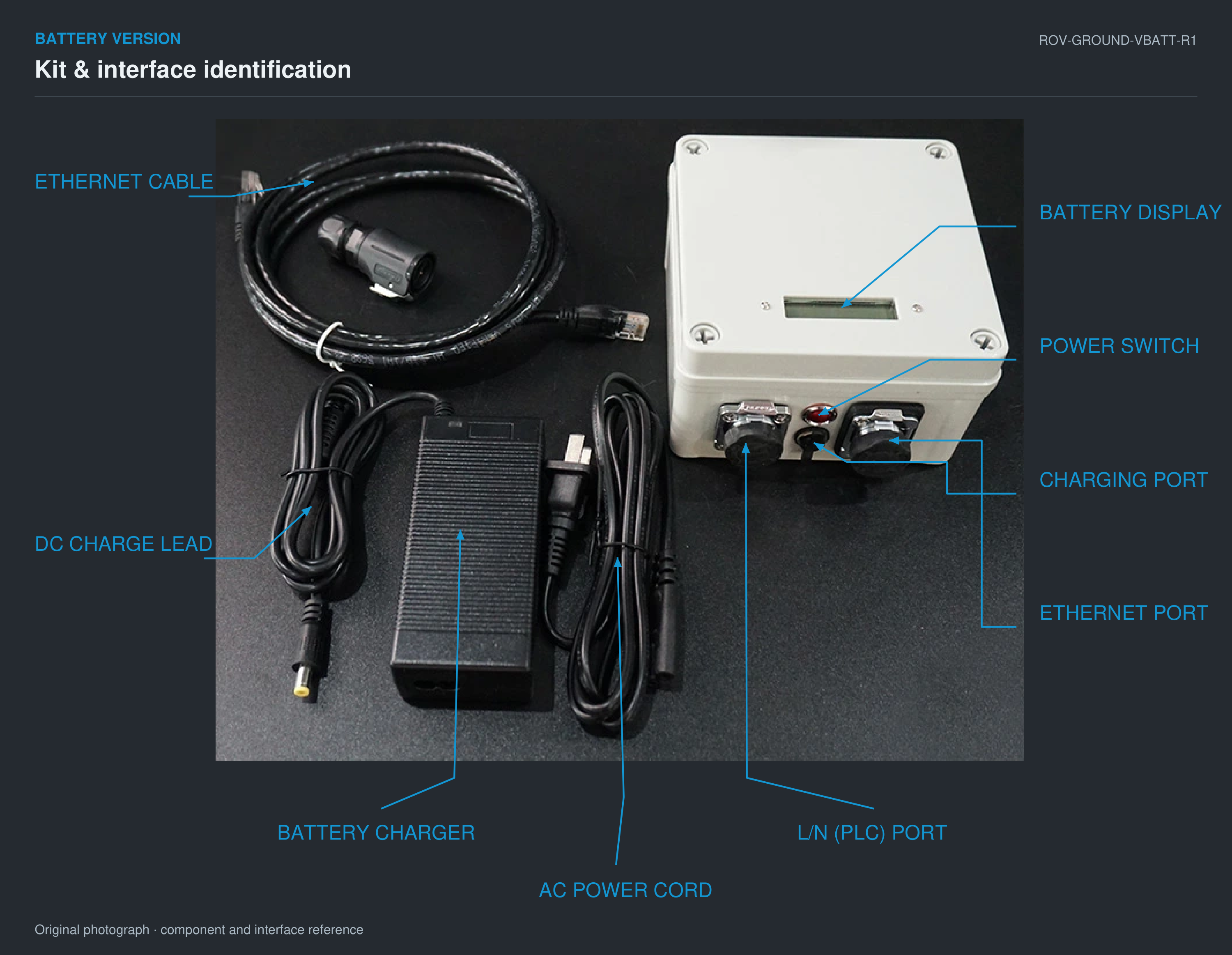
View labeled image in high resolution ↗
ROV-GROUND-VBATT-R1
Battery version kit
Self-powered interface with an internal battery and a dedicated charging connection.
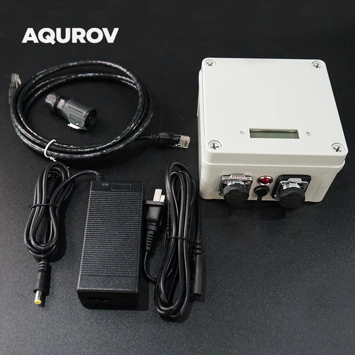
- Ethernet cable
- Battery charger with DC charging lead
- AC power cord
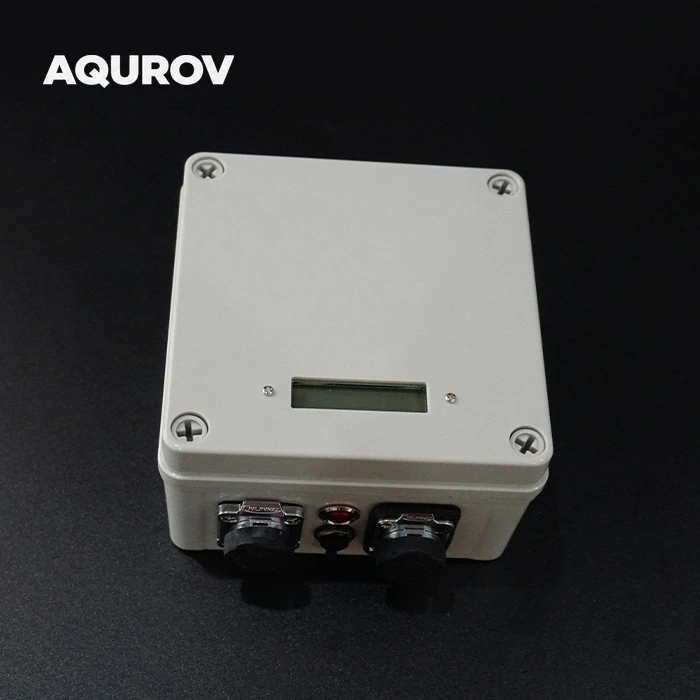
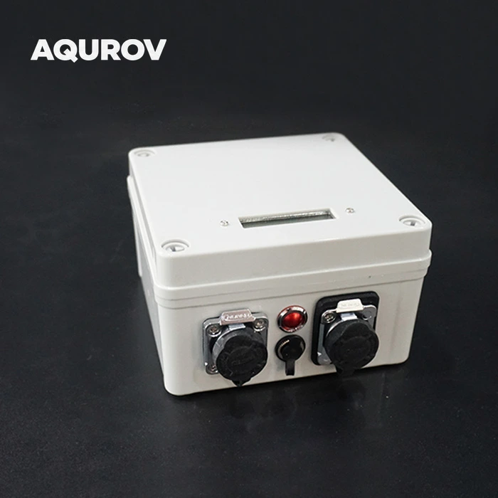
On the enclosure: battery display, power switch, charging port, L/N (PLC) port and Ethernet port.
View labeled image in high resolution ↗
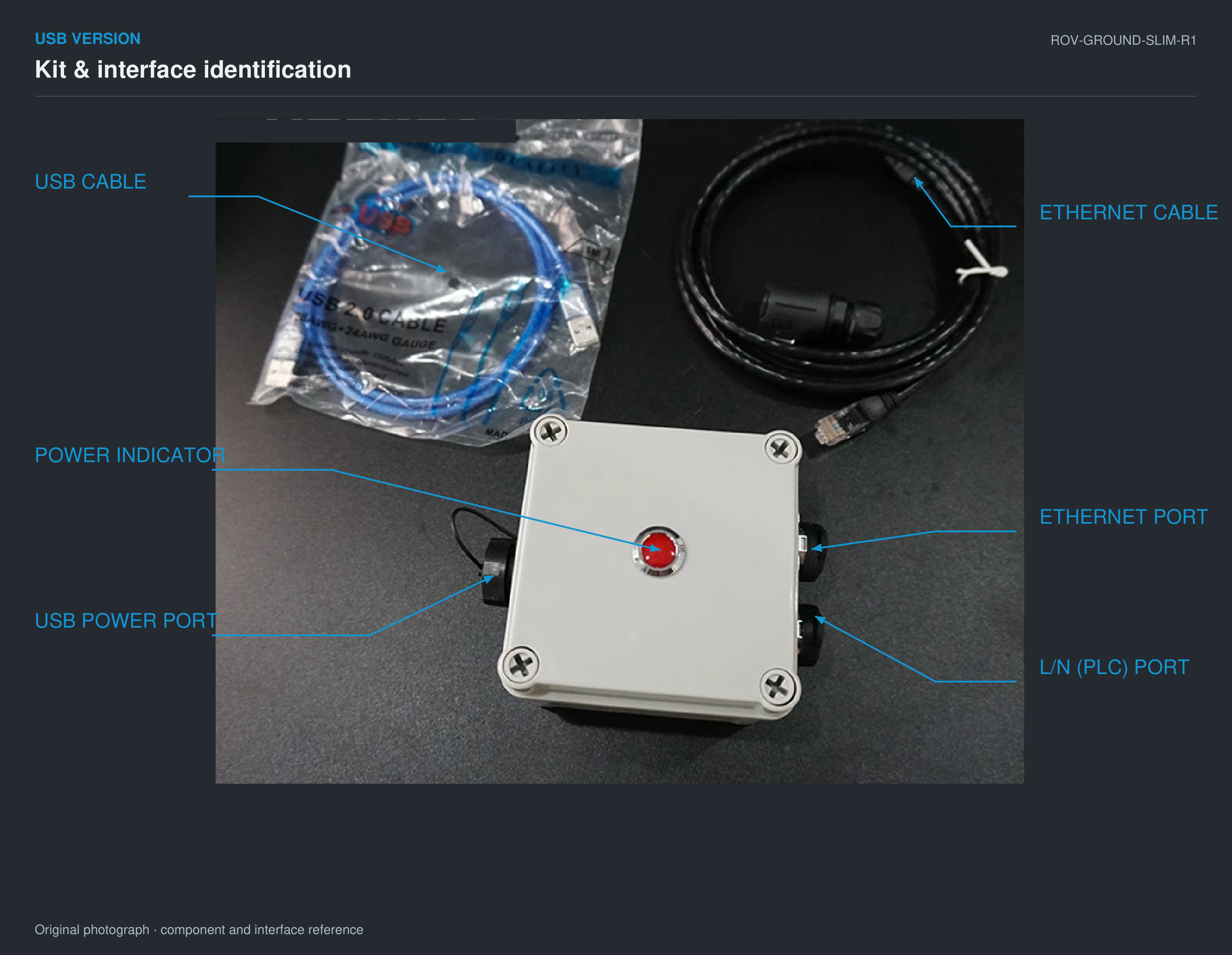
ROV-GROUND-SLIM-R1
USB version kit
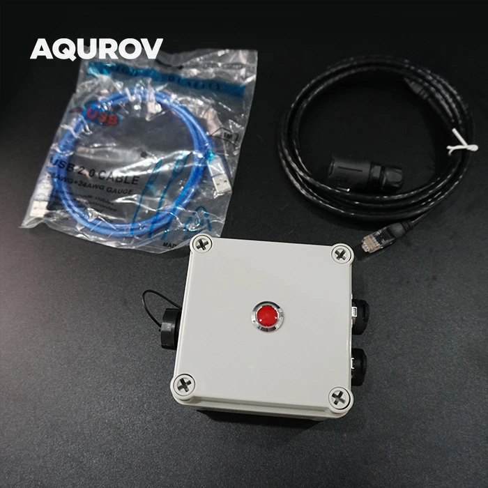
A lighter interface powered from a USB source at the control station.
- Ethernet cable
- USB cable
- PLC connector / plug
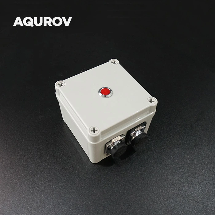
On the enclosure: USB power port, power indicator, Ethernet port and L/N (PLC) port.
View accessory details by version
| Battery version | Interface box, Ethernet cable, PLC connector / plug, charger and AC lead |
|---|---|
| USB-powered version | Interface box, Ethernet cable, PLC connector / plug and USB cable |
The ROV and control station in the connection example are separate equipment. A compatible robot-side PLC module is required for the communication link.
Engineering reference
English drawings for selection and installation planning
Original engineering geometry and dimension values retained, with English labels on the system example.
Selection & integration FAQ
Which version should I choose?
Choose the battery version for an independently powered interface with a battery display, switch and charging connection. Choose the USB version when USB power is available and you prefer the lighter 0.3 kg unit.
Does USB carry the robot’s Ethernet data?
The supplied description identifies USB as the power source for the USB version. The control station’s data connection is through the Ethernet interface.
What is needed inside the robot?
The robot needs a PLC module verified as compatible with this interface. Confirm the module pairing and tether connector wiring before integrating the two ends of the link.
Is 100 Mbps guaranteed over every 300 m tether?
The source reports up to 100 Mbps at 300 m within the same electricity-meter range. Throughput depends on the cable, electrical conditions and interference in the actual installation.
Can the box be submerged?
Use the box topside. The original listing describes resistance to rain and water drops, and specifically excludes underwater use.
What do the L/N labels mean?
The supplied wiring definition labels terminal 1 as L and terminal 2 as N. These are the named connections for the power-line communication signal; use the supplied connector views and a verified compatible system.
How many nodes are supported?
The product description states a maximum of eight nodes. The supported arrangement still depends on compatible modules and the communication installation.
Reviews
There are no reviews yet.