Description
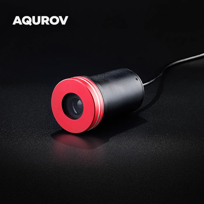
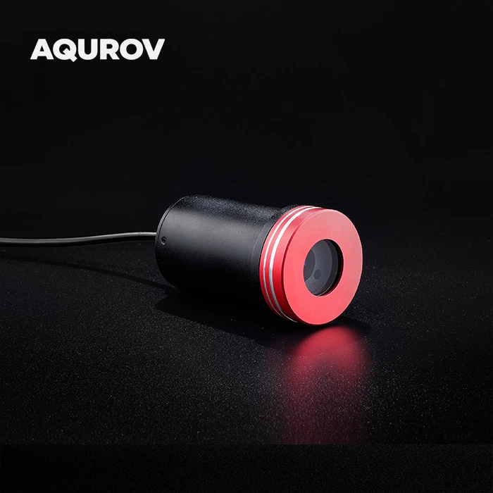
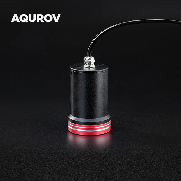
TOF underwater laser rangefinder
Optical distance sensing for inspection and integration
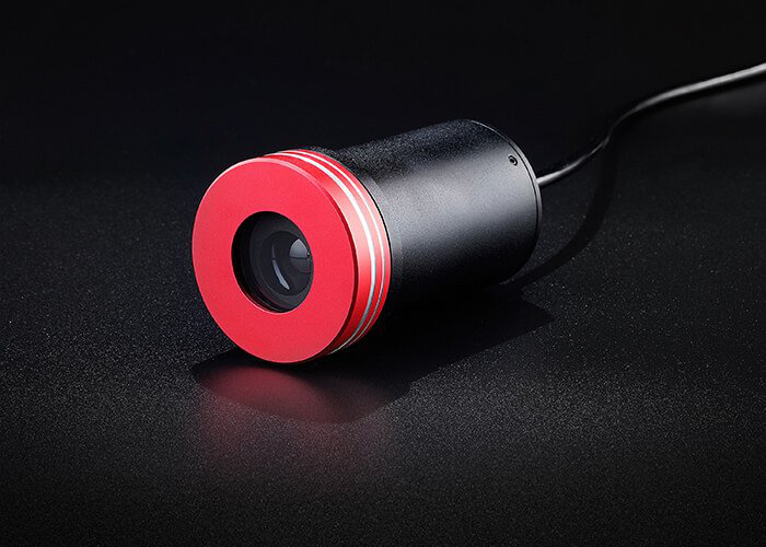
The TOF Laser Rangefinder measures distance using reflected laser light. Its phase-modulated ranging method provides an optical measurement option for underwater engineering and observation tasks.
Use the sensor as part of a system that can position the optical face toward a target and receive its distance data.
- 01Engineering inspectionSupport distance checks during underwater installation and maintenance.
- 02Vehicle integrationPlan an optical ranging sensor into an ROV or underwater inspection assembly.
- 03Observation and surveyAdd distance information to an underwater observation workflow.
Measure with a reflected optical signal.
A clear path between the sensor and the target
Send modulated light
The ranging system emits a modulated laser signal toward the surface to be measured.
Collect the reflection
Returned light carries the information used to estimate target distance.
Read the distance
The phase-modulated TOF method uses the returned optical signal to determine range.
Dimensions and rear threaded interface
Millimetres · original engineering drawing
| Cylindrical body diameter | Ø50 mm |
|---|---|
| Front collar diameter | Ø57 mm |
| Cylindrical section length | 71.50 mm |
| Housing length | 96 mm |
| Length to cable-gland end | 109.50 mm (reference) |
| Threaded-hole count | 4 |
|---|---|
| Thread designation | M4 |
| Thread depth | 6 mm |
| Hole pitch circle diameter | Ø30 mm |
The 109.50 mm dimension is shown in parentheses as a reference on the original drawing. Cable length is not specified by this drawing.
Check the envelope before integration.
Original dimensioned drawings · clear, high-resolution views
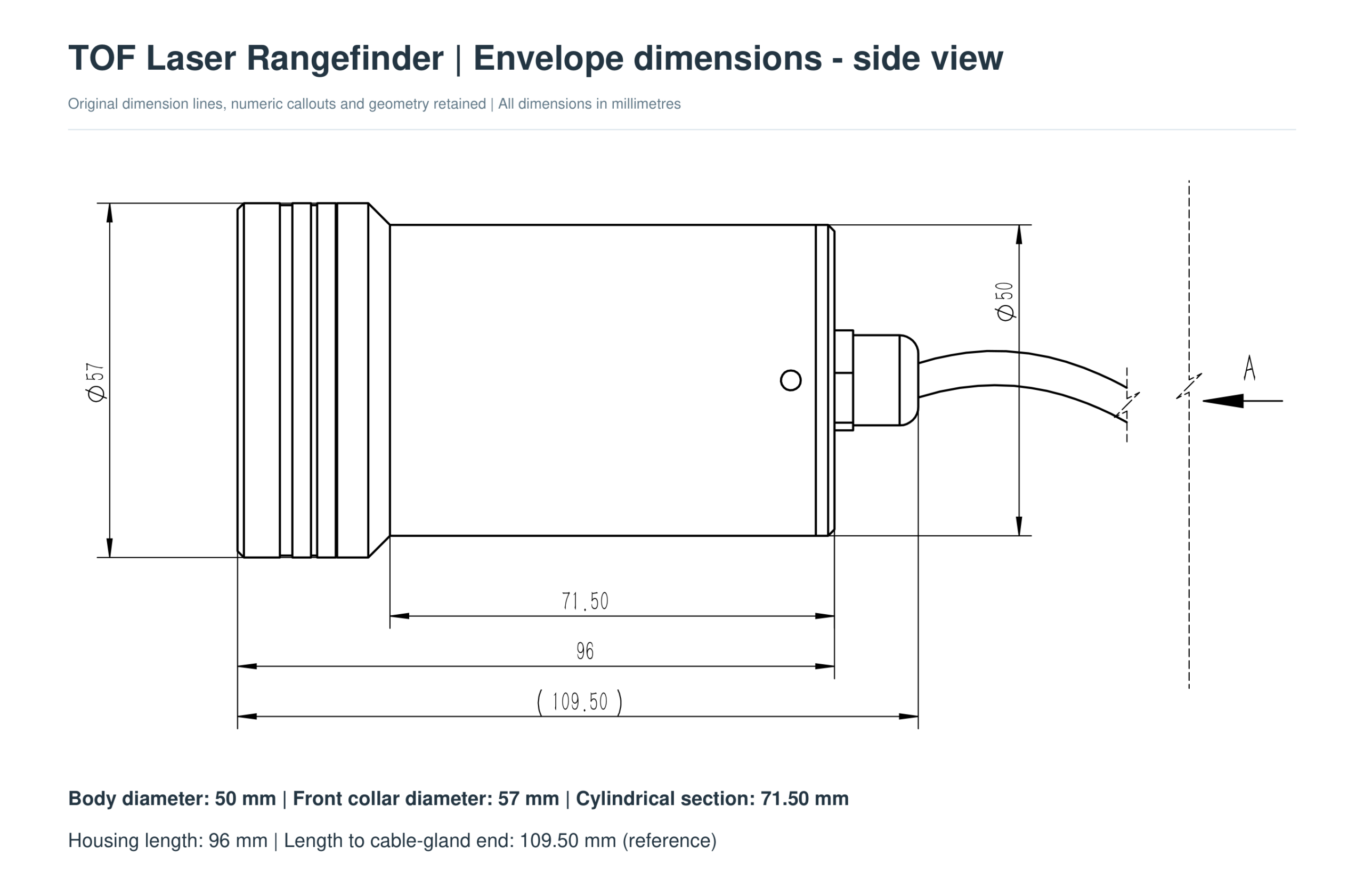
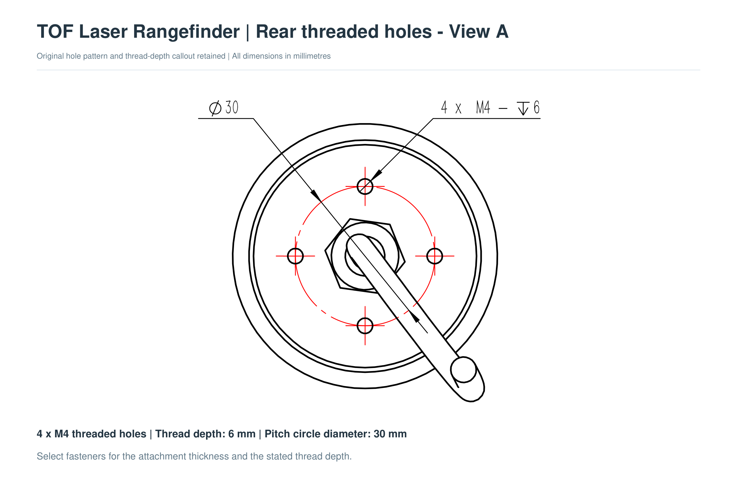
Match the rear threaded interface.
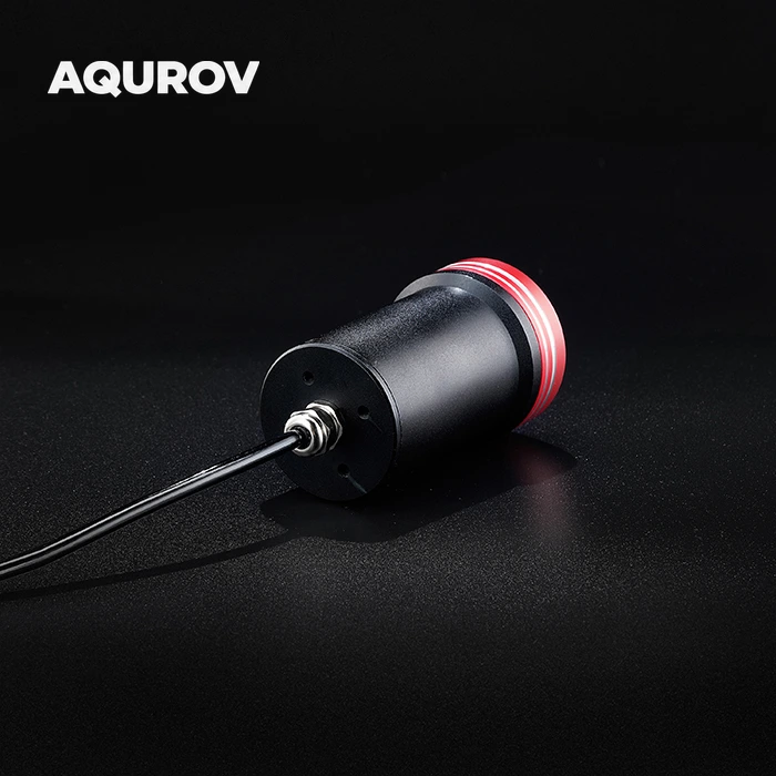
The original rear drawing defines four M4 threaded holes on a 30 mm pitch circle. Use the dimensioned PDF together with the STEP model to plan the attachment and surrounding assembly.
- Four M4 threaded holes
- Thread depth: 6 mm
- Hole pitch circle: Ø30 mm
- Housing length: 96 mm
Select screw length for the attachment thickness and stated thread depth. Allow space beyond the cable gland for the cable bend; the drawing does not specify the supplied cable length.
Plan the sensor installation.
Physical orientation and cable access
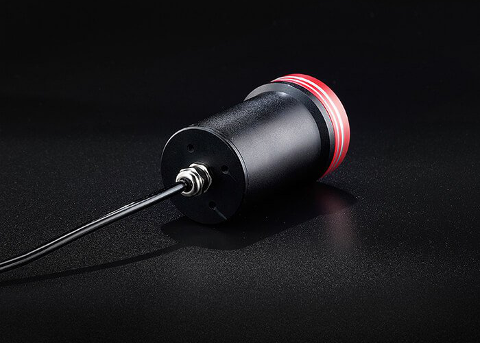
Arrange the housing around the task.
- Point the optical face toward the intended measurement target and keep the optical path unobstructed.
- Check the sensor envelope in the vehicle or inspection fixture.
- Leave room for the cable outlet and a suitable bend in the cable.
- Verify the finished unit’s supply, signal interface and wiring before connection.
Technical downloads
Drawings, module manual and CAD as separate files
The user manual describes the internal laser rangefinder module. Confirm the finished sensor’s external power supply and wiring before applying module-level electrical specifications.
Selection and integration FAQ
Questions to resolve before system integration
Is 60 m the operating depth?
The original listing uses 60 m as a ranging-distance claim. Operating depth is a separate housing-pressure specification; the two values should not be interchanged.
What affects underwater ranging performance?
The original description identifies underwater backscatter as a factor in target contrast, range and accuracy. Evaluate the actual water conditions, target and measurement direction for the application.
Does the 3D CAD model include electrical wiring?
The model describes physical geometry. It does not establish power-supply requirements, connector pinout, wire colours or software compatibility.
What are the rear threaded-hole dimensions?
The supplied dimension drawing specifies four M4 threaded holes, 6 mm thread depth, on a 30 mm pitch circle. Select fastener length for the attachment thickness and the specified thread depth.
What is included in the CAD download?
The ZIP contains one STEP file. The drawn cable is part of the source model and should not be interpreted as a supplied cable-length specification.
Does the manual specify the complete enclosed sensor?
The manual covers the internal laser rangefinder module and its serial protocol. Its bare-module dimensions and electrical ratings are separate from the enclosed sensor’s housing dimensions and external connection requirements.
Reviews
There are no reviews yet.