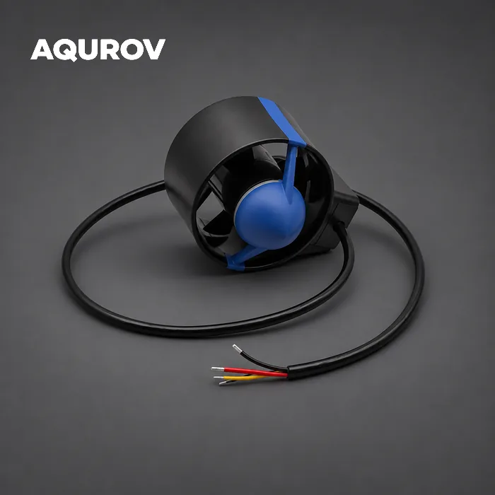
Description
Made for service in the field
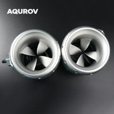
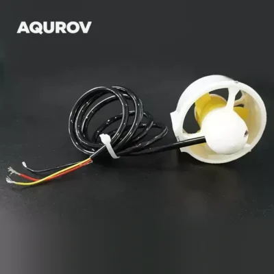
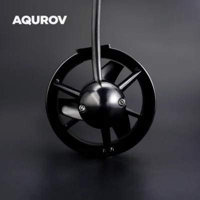
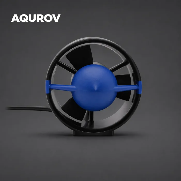
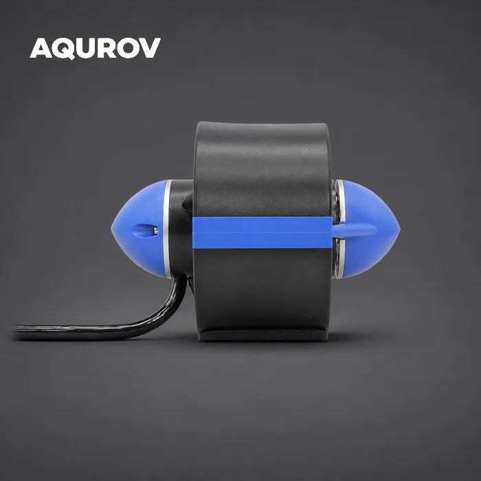
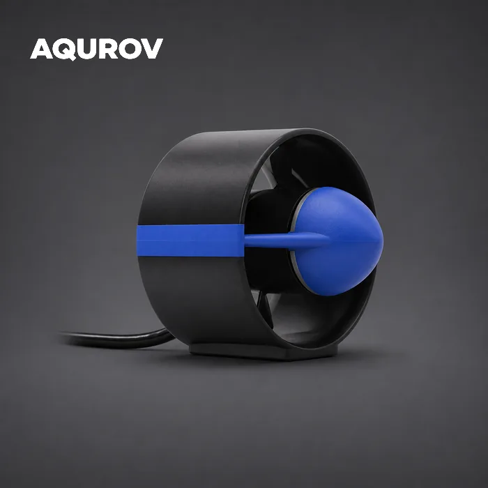
Images from five angles show the P150’s access, installation and supplied parts. Click a photo for its full-resolution source.
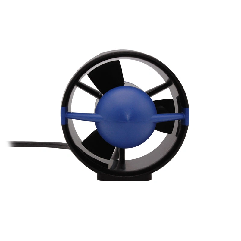
Service the propeller while the base stays mounted
The screwless quick-release design lets you replace the propeller or remove the protective screen without removing the thruster mounting base from the vehicle.
- Propeller and screen access without taking off the mount
- Removable protective screen included with the supplied kit
- Opposite rotation propeller supplied for your configuration
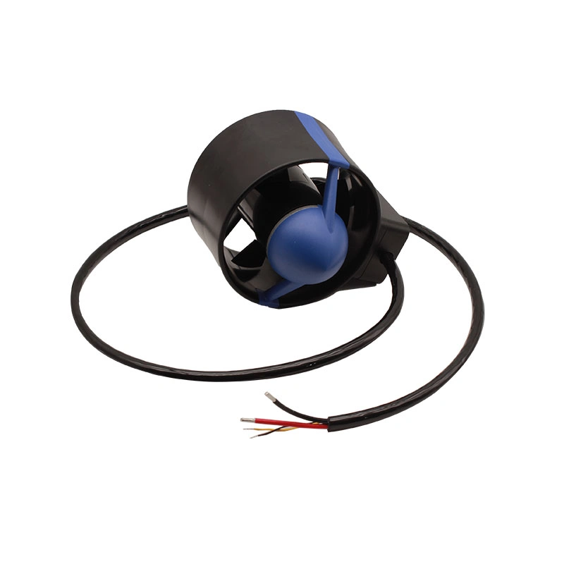
Route the cable around your vehicle
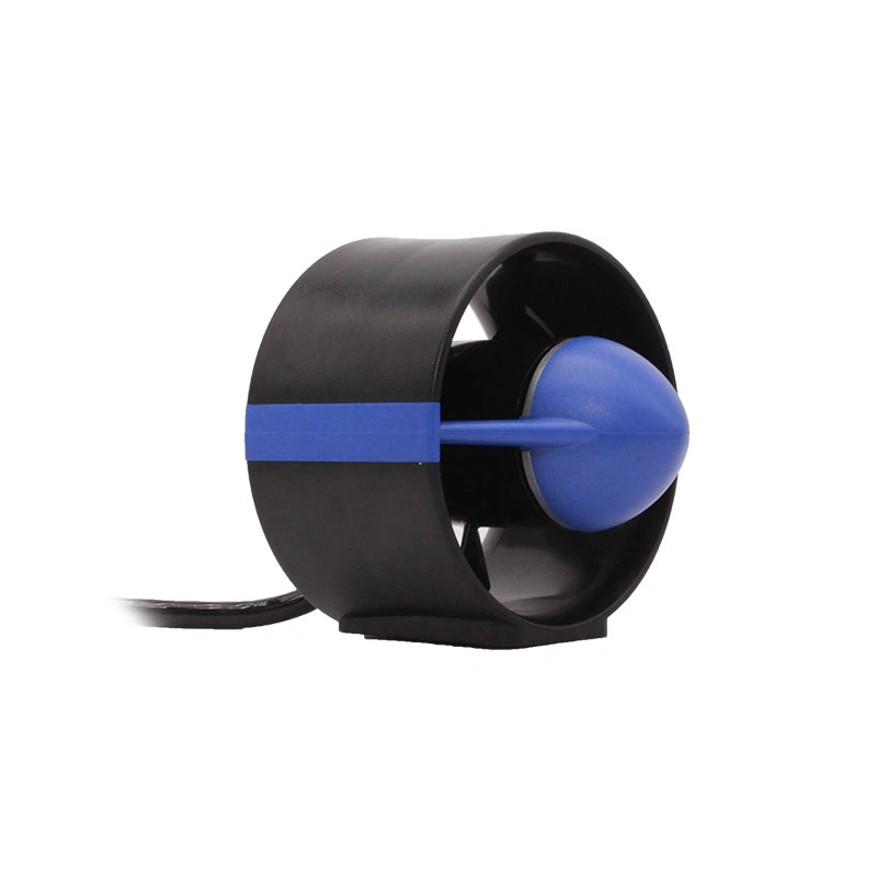
The full unit and attached cable are shown together so the bend, exit direction and available space can be planned against your mount and power enclosure. Use the dimensioned drawing for exact clearances.
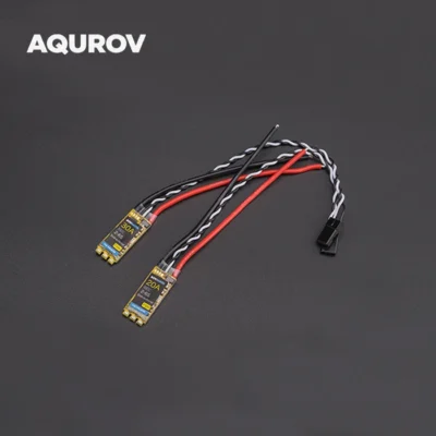
A compatible bidirectional ESC is required. Choose a with-ESC option or supply a compatible controller for a without-ESC option.
Applications
Comparing the P150 with the Blue Robotics T500?
For an ROV or USV project, compare the installation and service details that affect the build. The P150 offers a 48 V model option, screwless propeller access and a supplied protective screen set.
| Selection detail | AQUROV P150 | Blue Robotics T500 |
|---|---|---|
| Power platform | Separate 24 V and 48 V models | Published operating range: 7–24 V |
| Propeller service | Screwless quick-release access; base can stay installed | Manufacturer’s propeller-change guide uses a screwdriver and hex driver |
| Protective screen | Removable screen set supplied with this package | Not listed in the manufacturer’s standard contents |
| Propeller diameter | 100 mm | 114.5 mm |
| Mounting pattern | M4; 56 × 40 mm hole spacing | Four M4 mounting holes at 25 mm spacing, plus one M8 hole |
The mounting patterns differ; check drawings before adapting a bracket. For thrust and current, use the full performance tables below and account for the operating voltage, controller and protective screen.
P150 details are documented in the technical sheets below. T500 details reflect the manufacturer’s published specifications and propeller service guide. Verify the latest configuration before selecting a replacement.
P150 specifications
Shared specifications
| Parameter | 24 V and 48 V |
|---|---|
| Overall dimensions | 121 × 161 × 140 mm |
| Propeller diameter | 100 mm |
| Mounting threads | M4 |
| Mounting hole spacing | 56 × 40 mm |
| Weight in air, with cable, without ESC | 1.0 kg |
| Weight in water, with cable, without ESC | 520 g |
| Cable outer diameter | 8.5 mm |
| Conductor cross section | 3 mm² |
| Thruster depth rating, supplier stated | 300 m |
| Specified maximum torque | 3.6 N·m |
For reference, the supplier listing gives 1.2 kg in air and 650 g in water, both including the cable, for its ESC-equipped configuration. Choose a with-ESC or without-ESC variation; the weight values above refer to the thruster without ESC.
24 V and 48 V model comparison
| Parameter | 24 V | 48 V |
|---|---|---|
| Supplier model reference | MOT-P150ESC-24V | MOT-P150ESC-48V |
| Operating voltage | 24 V | 48 V |
| Cable length, model listing | >90 mm | >90 mm |
| Peak forward / reverse thrust, screen removed | 7.68 / 13.44 kgf | 15.2 / 14.32 kgf |
| Current at the peak thrust test point | 52 A | 40 A |
| Specified maximum current | 80 A | 40 A |
| Specified maximum power | 1,900 W | 2,000 W |
| Motor Kv, no load | 488 rpm/V | 244 rpm/V |
| Maximum speed, no load | 9,500 rpm | 11,716 rpm |
Both technical sheets specify a cable length greater than 90 mm. Confirm the supplied lead length if your installation requires a fixed reach. Peak thrust depends on the ESC used for the test.
36 V reference in the 48 V technical sheet
| Parameter | At 36 V |
|---|---|
| Peak forward / reverse thrust, screen removed | 13.6 / 11.12 kgf |
| Maximum current | 40 A |
| Maximum speed | 8,785 rpm |
Thrust and current by pulse width
Compare pulse width, thrust and current for each rotation direction with the screen removed. Drive electronics and installation affect the results.
24 V test data 22 test rows
| Left rotation | Right rotation | ||||
|---|---|---|---|---|---|
| Pulse width | Thrust (kgf) | Current (A) | Pulse width | Thrust (kgf) | Current (A) |
| 1378 | 0.8 | 2 | 1620 | 1.44 | 2 |
| 1349 | 1.44 | 4 | 1646 | 2.4 | 4 |
| 1323 | 2 | 6 | 1667 | 3.2 | 6 |
| 1297 | 2.56 | 8 | 1695 | 4.4 | 8 |
| 1281 | 2.88 | 10 | 1712 | 5.04 | 10 |
| 1267 | 3.28 | 12 | 1724 | 5.6 | 12 |
| 1251 | 3.6 | 14 | 1739 | 6.24 | 14 |
| 1242 | 3.92 | 16 | 1750 | 7.12 | 16 |
| 1224 | 4.16 | 18 | 1759 | 7.52 | 18 |
| 1213 | 4.48 | 20 | 1771 | 7.84 | 20 |
| 1203 | 4.96 | 22 | 1785 | 8.64 | 22 |
| 1189 | 5.28 | 24 | 1793 | 8.96 | 24 |
| 1179 | 5.44 | 16* | 1807 | 9.36 | 16* |
| 1169 | 5.6 | 28 | 1819 | 9.84 | 28 |
| 1156 | 5.84 | 30 | 1830 | 10.32 | 30 |
| 1143 | 6 | 32 | 1840 | 10.56 | 32 |
| 1136 | 6.24 | 34 | 1852 | 10.96 | 34 |
| 1124 | 6.4 | 36 | 1867 | 11.12 | 36 |
| 1113 | 6.48 | 38 | 1875 | 11.44 | 38 |
| 1104 | 6.96 | 40 | 1887 | 11.76 | 40 |
| 1090 | 7.28 | 42 | 1899 | 12.08 | 42 |
| 1000 | 7.68 | 52 | 2000 | 13.44 | 52 |
* The technical sheet lists 16 A for both directions at pulse widths 1179 and 1807. Confirm this row with the supplier before using it for design calculations.
48 V test data 11 test rows
| Left rotation | Right rotation | ||||
|---|---|---|---|---|---|
| Pulse width | Thrust (kgf) | Current (A) | Pulse width | Thrust (kgf) | Current (A) |
| 1388 | 1.92 | 2 | 1534 | 1.92 | 2 |
| 1357 | 4.4 | 6 | 1562 | 4.16 | 6 |
| 1339 | 6 | 10 | 1580 | 6.08 | 10 |
| 1320 | 8 | 16 | 1599 | 8.24 | 16 |
| 1302 | 9.52 | 22 | 1615 | 10.08 | 22 |
| 1292 | 10.4 | 26 | 1624 | 11.12 | 26 |
| 1282 | 12 | 30 | 1632 | 11.76 | 30 |
| 1272 | 13.2 | 34 | 1642 | 13.68 | 34 |
| 1268 | 13.92 | 36 | 1647 | 13.84 | 36 |
| 1263 | 14.8 | 38 | 1651 | 14.08 | 38 |
| 1259 | 15.2 | 40 | 1656 | 14.32 | 40 |
36 V reference data 13 test rows
| Left rotation | Right rotation | ||||
|---|---|---|---|---|---|
| Pulse width | Thrust (kgf) | Current (A) | Pulse width | Thrust (kgf) | Current (A) |
| 1374 | 1.52 | 2 | 1550 | 1.36 | 2 |
| 1335 | 3.76 | 6 | 1584 | 3.04 | 6 |
| 1322 | 4.72 | 8 | 1596 | 3.76 | 8 |
| 1312 | 5.52 | 10 | 1607 | 4.56 | 10 |
| 1301 | 6.32 | 12 | 1615 | 5.2 | 12 |
| 1277 | 8.32 | 18 | 1639 | 6.88 | 18 |
| 1264 | 9.44 | 22 | 1651 | 7.84 | 22 |
| 1251 | 10.24 | 26 | 1663 | 8.72 | 26 |
| 1238 | 11.2 | 30 | 1674 | 9.52 | 30 |
| 1233 | 11.6 | 32 | 1679 | 10.08 | 32 |
| 1221 | 12.56 | 36 | 1691 | 10.88 | 36 |
| 1217 | 13.36 | 38 | 1696 | 11.04 | 38 |
| 1213 | 13.6 | 40 | 1702 | 11.12 | 40 |
Sources: P150ESC 24 V technical sheet dated June 26, 2026 and 48 V technical sheet dated May 14, 2026. Performance depends on the controller and installation.
Dimensions and assembly
Dimension drawing
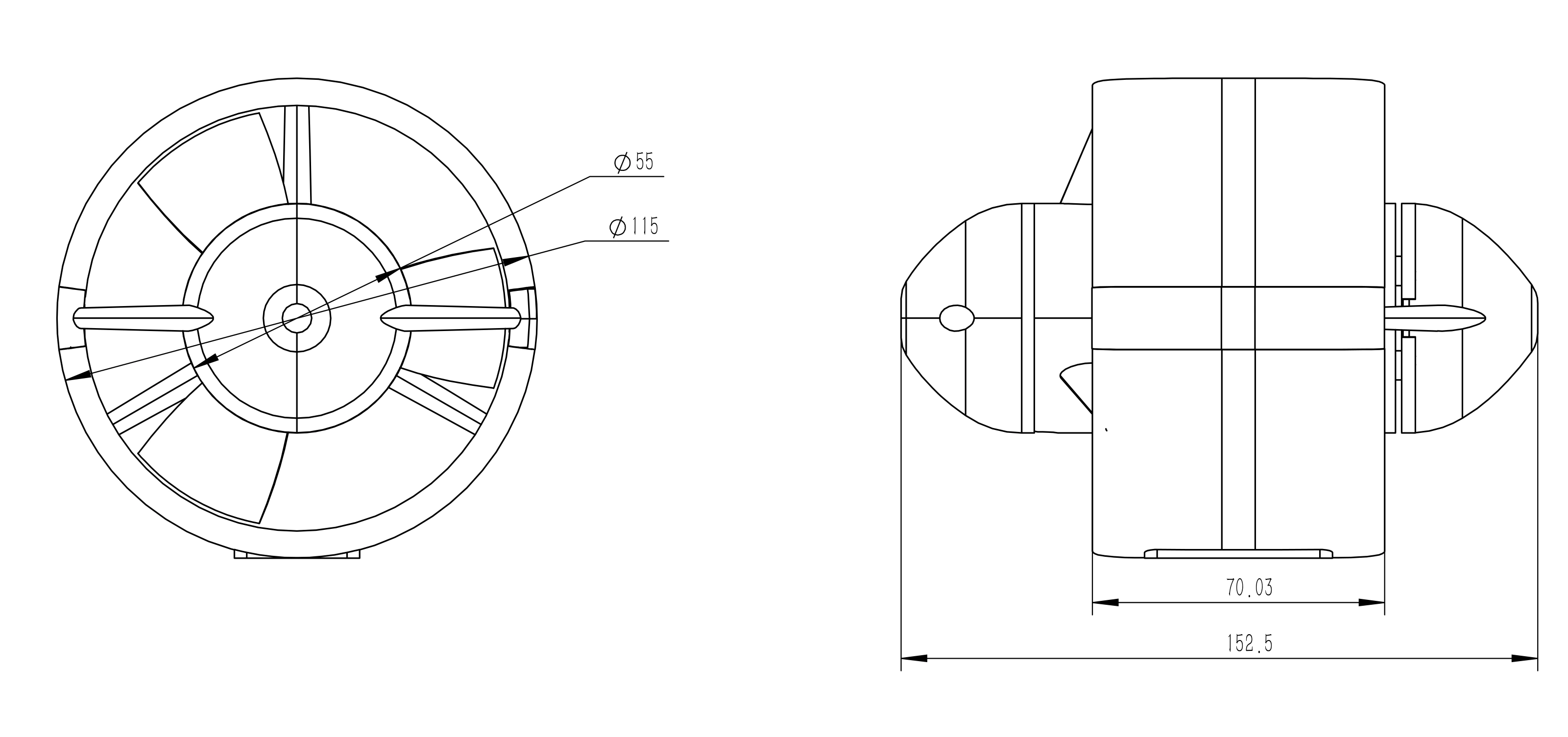
Plan the mounting interface
- Mounting threads
- M4
- Mounting hole spacing
- 56 × 40 mm
- Propeller diameter
- 100 mm
- Listed overall envelope
- 121 × 161 × 140 mm
Callouts on the drawing
Ø55 mm · Ø115 mm · 70.03 mm · 152.5 mm
These callouts are shown in the front and side views. Use the original PDF to identify the reference points and confirm production dimensions before machining a mount.
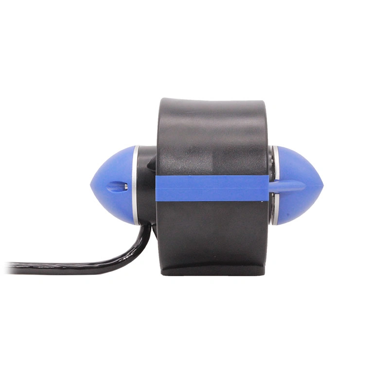
Check the housing from the side
This view shows the duct depth, blue nose cones and cable exit. Compare it with the large dimensioned drawing above before routing cable or machining a mount.
Mounting threads: M4 · hole spacing: 56 × 40 mm · propeller: 100 mm.
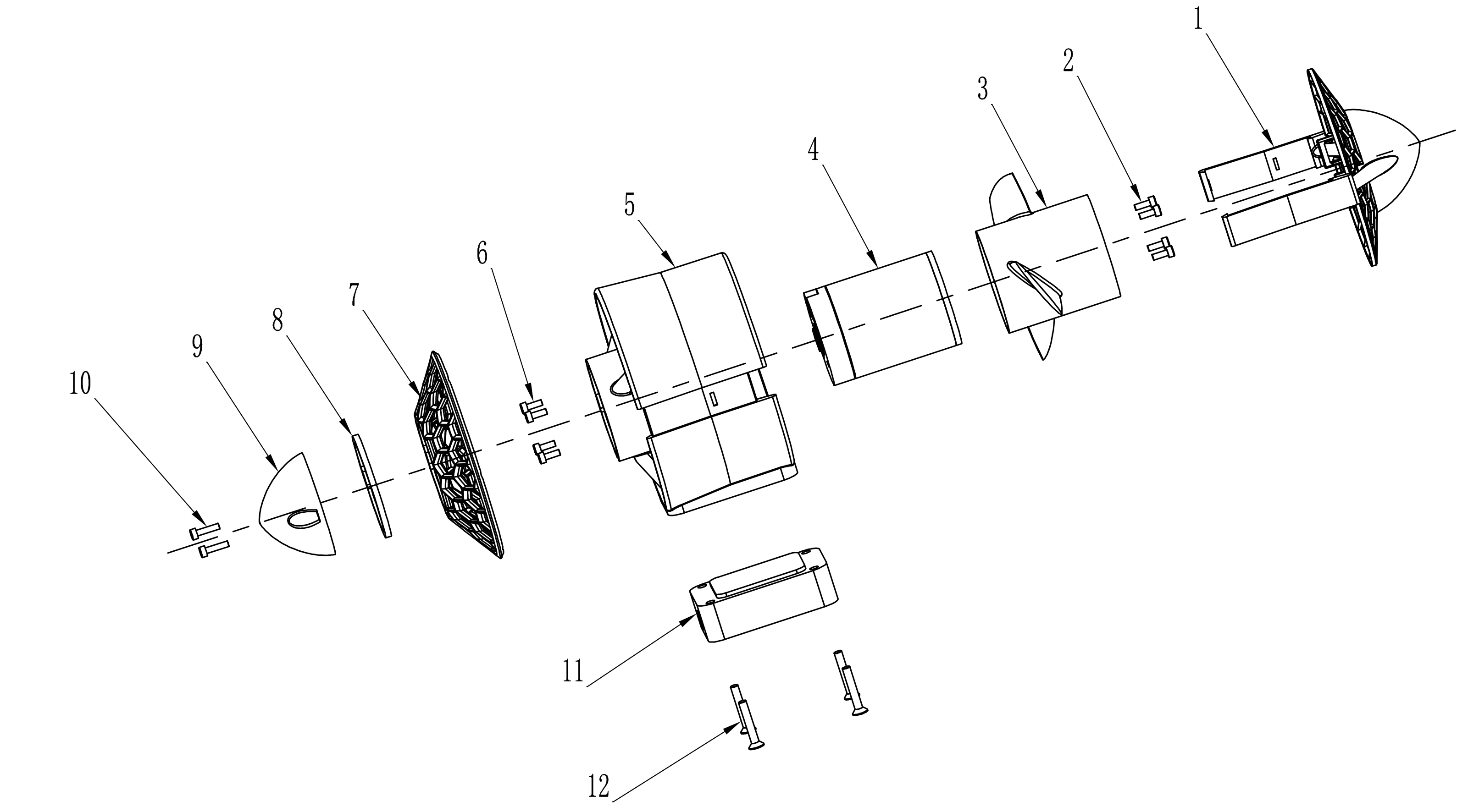
Exploded assembly drawing
Everything supplied with the P150
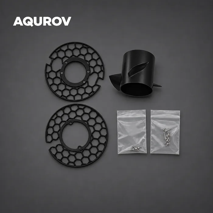
Choose 24 V or 48 V, then select with or without ESC. The photo shows the thruster and supplied accessories; ESC inclusion follows the selected option.
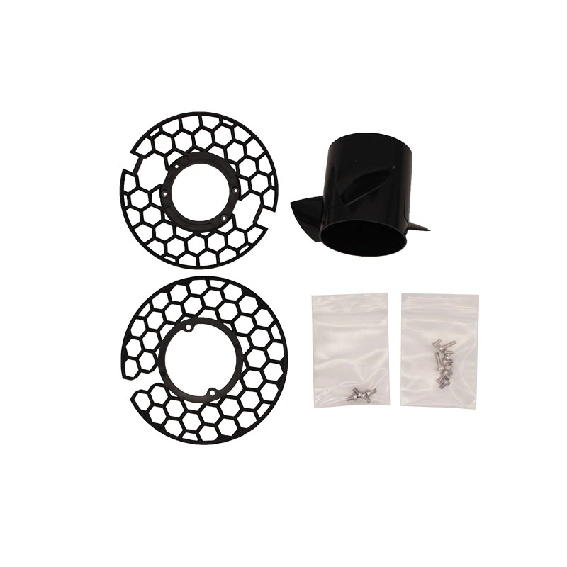
| Item | Quantity |
|---|---|
| P150 thruster, selected voltage | 1 unit |
| Removable protective screen | 1 set |
| Opposite rotation propeller | 1 piece |
| Screws | 1 set |
| ESC | 1 unit, with-ESC option only |
Choose the ESC configuration
The with-ESC option includes a controller; the without-ESC option requires a compatible bidirectional controller supplied by you. Verify the selected ESC’s voltage, current and installation ratings for your system.
Technical downloads
Open a PDF to preview it in your browser. Use the viewer’s download button to save a copy.
Engineering drawing
Dimensioned front and side views, plus an isometric view.
Exploded assembly drawing
Component layout and assembly reference for the P150-LA-300.
24 V technical specification
Supplier specifications and the 24 V thrust and current test table.
48 V technical specification
Supplier specifications and the 48 V and 36 V reference test tables.
Frequently asked questions
How does the P150 compare with a T500 thruster?
The P150 offers a separate 48 V model, screwless access to its propeller with the base installed, and a removable protective screen in this package. Its mounting pattern differs from the T500. Compare the drawings and full performance tables when selecting a thruster for your system.
What comes in the box?
One P150 thruster in the selected voltage, one protective screen set, one opposite rotation propeller and one screw set. An ESC is included only with the selected with-ESC option.
What can I remove without taking the mount off?
The screwless quick-release design lets you replace the propeller and screen with the mounting base still on the vehicle. Disconnect power before handling the propeller.
How do I pick the voltage and ESC?
Choose the 24 V or 48 V version to suit your power system. Check the controller’s input voltage range, continuous current and cooling. The 24 V version’s 80 A specified maximum and 52 A measured peak thrust point describe different conditions. Set current limits to suit the selected ESC.
Can I mount the ESC outside the electronics enclosure?
A compatible bidirectional PWM ESC can control forward and reverse. An external controller designed for submerged use can free up enclosure space and dissipate heat into the water. Check the specific ESC’s immersion and depth ratings before installing it outside the enclosure.
Does fitting the screen change the thrust?
Yes. The supplied test tables show the thruster with the screen removed. The supplier notes that fitting the screen may reduce thrust by around half and slightly increase current. Allow for the screen when sizing the propulsion system.
What depth is the thruster rated for?
The supplier lists a 300 m depth rating for the thruster. Assess the controller, cable termination and enclosure for the planned operating depth.
Where can I check mounting dimensions?
Use the engineering drawing and exploded assembly drawing in Technical downloads. The product listing specifies M4 mounting threads and 56 × 40 mm hole spacing. Confirm the production drawing and clearances before machining a bracket.
Three-quarter view
Front view
Side profile
Thruster and cable
Included accessories